USB_CH341_E22P
An Ebyte E22P-868M30S 1 W LoRa module on any USB port
49.22 × 63.54 mm · two layers · CH341F bridge · meshtasticd ready
1. Overview
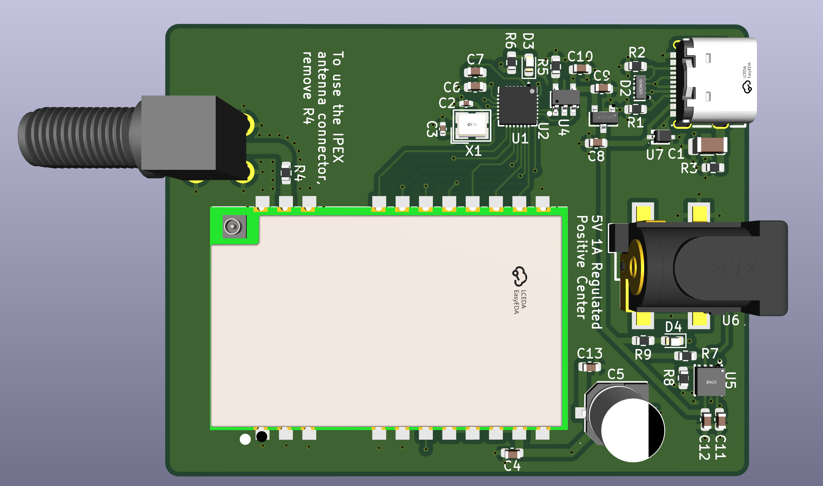
A USB-to-SPI adapter that brings an Ebyte E22P-868M30S — an SX1262 with a power amplifier, up to 30 dBm — to meshtasticd on any PC or Raspberry Pi, with no GPIO header needed. The bridge is a CH341F running in UIO mode, which is what the libch341-spi-userspace driver in Meshtastic speaks.
Key features
- Plugs a 1 W LoRa module into a USB port — no SPI header, no GPIO, no soldering to the host
- Pin mapping matches the official Meshtastic preset, so the board works with a stock config file
- A TPS2115A power mux takes 5 V from either USB or a DC jack, and the choice is deterministic rather than a voltage comparison
- With the jack plugged in the module runs at full power; on USB alone the port is not asked for more than it can give
- A front-panel LED tells you which of the two supplies is feeding the radio
- SMA connector and an IPEX pad on the module, selectable by moving one 0 Ω resistor
- Two layers, 1.6 mm, nothing outside standard fabrication limits
2. Pinout
The CH341 exposes its data lines as UIO pins D0–D7. This is how they land on the LoRa module, and how meshtasticd refers to them:
| CH341 pin | UIO line | E22P pin | config.yaml | Direction |
|---|---|---|---|---|
| 15 | D0 | 19 NSS | CS: 0 | output |
| 16 | D1 | 6 EN | RXen: 1 | output |
| 17 | D2 | 15 NRST | Reset: 2 | output |
| 18 | D3 | 18 SCK | — | output |
| 19 | D4 | 14 BUSY | Busy: 4 | input |
| 20 | D5 | 17 MOSI | — | output |
| 21 | D6 | 13 DIO1 | IRQ: 6 | input (fixed) |
| 22 | D7 | 16 MISO | — | input (fixed) |
In UIO mode the direction of D0–D5 is set by software; D6 and D7 are always inputs. That is why MISO and the packet interrupt sit on the last two lines. DIO2 on the module is bridged to its T/R CTRL pin, so the radio drives its own RF switch — which is what DIO2_AS_RF_SWITCH enables.
3. Bill of Materials
| Ref | Part | Package | LCSC | Purpose |
|---|---|---|---|---|
| U1 | CH341F | QFN-28 | C412870 | USB to SPI bridge |
| U2 | 24C02 | SOT-23-5 | C18723540 | Configuration EEPROM (VID/PID/mode) |
| U3 | E22P-868M30S | SMD module | — | SX1262 LoRa radio with PA |
| U4 | XC6206P332MR | SOT-23-3 | C5148692 | 3.3 V LDO for the bridge |
| U5 | TPS2115ADRBT | SON-8 | C2863458 | Power mux, USB or DC jack |
| U6 | DC-005-2.5A | THT | C2880544 | 5 V jack with switch contact |
| U7 | H7VHD3UA | SOD-323 | C20615807 | TVS on VBUS |
| D2 | TPD4E05U06 | USON-10 | C138714 | USB ESD protection |
| USB1 | KH-TYPE-C-16P | SMD | C709357 | USB-C receptacle |
| X1 | 12 MHz | 3.2 × 2.5 mm | C9002 | Bridge crystal |
| C5 | 470 µF / 16 V | Ø6.3 mm | C42436549 | Solid polymer, 28 mΩ — TX current reservoir |
Generic passives are left without a part number on purpose, so the assembler can pick them from stock. The LoRa module and the SMA connector are sourced separately.
4. Design Notes
Why there is a DC jack at all
The module draws 600–670 mA while transmitting at 30 dBm, which is more than a USB port is obliged to deliver. So the board takes power from either source and switches between them with a rule that does not depend on which one happens to sit at a higher voltage:
| USB | Jack | Active source | LED |
|---|---|---|---|
| ✅ | ❌ | USB — run at reduced power | off |
| ✅ | ✅ | Jack — full power | on |
| ❌ | ✅ | none, output is high-Z | — |
| ❌ | ❌ | none, output is high-Z | — |
The jack's switch contact drives one of the mux control pins, with its pull-up referenced to VBUS. That single detail makes the signal mean "there is a jack and there is USB", which buys two things: with the jack in, the jack always wins, and with the host unplugged the radio is left unpowered instead of sitting alive next to a dead bridge.
The LED is not decoration
It hangs off the mux status pin, which is open-drain and pulls low when the jack input is the one switched through. So a lit LED means the radio is eating from the jack and can transmit at full power; dark means it is on USB.
What is protected, and what is not
The USB side has a TVS on VBUS and a four-channel ESD device across D+, D−, CC1 and CC2. The DC jack has neither. The module is damaged above 5.5 V and the mux is rated to 6 V absolute maximum, so a 9 or 12 V adapter, or a centre-negative one, will destroy both. Use 5 V and check the polarity.
5. Fabrication
| Board size | 49.22 × 63.54 mm |
| Layers | 2, 1.6 mm FR4 |
| Vias | 0.6 / 0.3 mm |
| Surface finish | HASL or ENIG |
| Files | Gerbers, drill, BOM and pick-and-place in the repository |
Nothing on the board falls outside standard fabrication limits. The design rule check passes clean, but be aware that no one has soldered one of these yet — see the note at the top of the page.
6. GitHub Repository
The complete KiCad 10 project, the fabrication files and the documentation are published on GitHub. KiCad embeds symbols and footprints in the project files, so it opens on any machine without installing extra libraries.
7. Using It with Meshtastic
The pin mapping matches the official lora-usb-meshtoad-e22.yaml preset, so a stock configuration works:
Lora:
  Module: sx1262
  CS: 0
  RXen: 1
  Reset: 2
  Busy: 4
  IRQ: 6
  spidev: ch341
  DIO2_AS_RF_SWITCH: true
  DIO3_TCXO_VOLTAGE: true
  USB_VID: 0x1A86
  USB_PID: 0x5512
  # On USB alone, keep the port within its budget:
  # SX126X_MAX_POWER: 10
One thing to know before you plug it in: the EEPROM has to be programmed with mode 0x12, or the bridge enumerates as a plain serial port instead of the parallel/synchronous device the driver expects. It is written over USB with CH341CFG or IMSProg.
meshtasticd cannot tell whether the DC jack is plugged in, so SX126X_MAX_POWER is a fixed setting rather than something the daemon adapts. If the board will live on USB alone, lower it.
← Back to Projects